Dismantlement Investigation
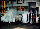
A pair of the High Frequency Generators of the Yosami Radio Transmitting Station completed their missions, and one is to be stored in the Yosami Radio Transmitting Station Memorial Museum to be built, and the other to be scrapped. Prior to the scrapping, the Tokai Chapter of the Institute of Electronics, Information and Communication Engineers conducted a dismantlement investigation to investigate the structure for two days, making a DVD report, and detailed survey drawings in 2007.
Purpose
Since the Yosami Radio Transmitting Station was returned from U.S. Navy to Japan in 1994, the interests toward the facility among local people and researchers of the Institute of Electronics, Information and Communication Engineers, or of industrial heritage, rose, especially toward the High Frequency Generators installed. They were then thought to be the type of Swedish-American electrical engineer Ernst Frederick Werner Alexanderson (1878-1975). Yet, they were not confirmed, because they were German-made, and the structures inside were not known. Thus, taking this opportunity, the Tokai Chapter of the Institute of Electronics, Information and Communication Engineers decided to carry a dismantlement investigation to clarify the type of the Generator.
Dates of Investigation
March 6-7, 2006
Procedures
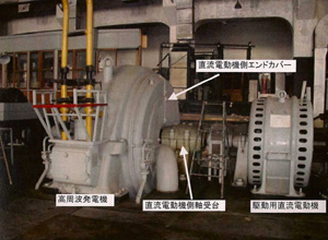
- 1.Bolts jointing the High Frequency Generator and driving Main D.C. Motor are dismantled to separate the two, and the cover of the High Frequency Generator is removed (Photo 1)
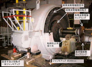
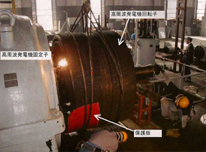
- 2.In order to remove the Rotator, the High Frequency Generator, partially berried on the floor, is lifted by some 30cm by crane truck to reveal the shapes of the Rotator and Stator (Photo 2)
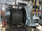
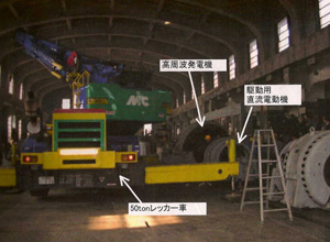
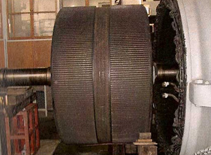
- 3.The Rotator is to be pulled off by crane truck in opposite of the Main D.C. Generator. The gap between the Rotator and the Stator is as minutely as 1mm, a glass fiber preventive sheet is inserted between the two, and as much as a half-day time is spent for pulling off (Photos 3 and 4)
- 4.After the Rotator being pulled off, magnetic poles or teeth are seen around the both sides of the outer circumferences, over the dented center belt. The number of magnetic poles is counted as 256 teeth (Photo 5)
1
2
3
4
5
Data
Weight of the High Frequency Generator 38 tons
Rotator, inside, weight 21 tons
Diameter 1.87 m, with the Barrel diameter of 1.1m
Survey drawings
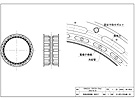
Figure 1: Assembly Drawing of the High Frequency Generator, by Shoji Ishida, the Chubu Society for the Industrial Heritage
Figure 2: Assembly Drawing of the Rotator and Stator, by Shoji Ishida, the Chubu Society for the Industrial Heritage
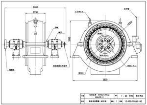
Figure 1
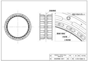
Figure 2


